
Design and implementation of the dual-center programming platform for ternary optical computer and electronic computer

The experiments were carried out on the dual-center model including electronic computer and TOC-SD16. Electronic computer is 64-bit windows 10 operating system, Intel(R) Core(TM) i7-8565U CPU @ 1.80 GHz 8 GB. In TOC-SD16, for easy viewing of the resulting data, three adjacent pixels in the same row form a processor bit. Each pixel may output horizontal polarized light (H) or vertical polarization light (V) or no-light (W), the light intensity of W, H and V may be different. For an identical processor bit, there is only one output (W or V or H). The appearance of a basic module of TOC-SD16 is shown in Fig. 8. Processor bits are symmetrical. The processor bits structure in SD16 is shown in Fig. 9.

The appearance of a basic module of SD16.

Liquid crystal divisions 8.
Experimental instance: for four computational tasks, it contains four calculations with simple data type: P1 = a + b and P2 = c − d, P3 = e∧g and P4 = h∨i. Here “P1 = a + b” is the addition operation, the augend a and addend b are 8-bit MSD numbers, the sum is P1, and there are 200,000 pairs of original data. “P2 = c − d” is the subtraction operation, the minuend c and subtrahend d are 8-bit MSD numbers, the difference is P2, and there are 200,000 pairs of original data. “P3 = e∧g” means logical “AND” operation, the result is assigned to P3, “P4 = h∨i” is logical “OR” operation, the result is assigned to P4. Here e, g, h and i are 8-bit three-valued data, there are 100,000 pairs of original data e and g and 100,000 pairs of original data h and i. The result is P3 which is one of the value of the set A, B, C. The set of the result P4 is one in X, Y, Z. The instance information is contained in ZHSL.SZG file.
In the experiment, two computing cores is connected via USB. The experiment process is as follows.
(1) Install auxiliary plug-in SZGX in user’s electronic computer, run the initial SZG file software to generate ZHSL.SZG file, for the generation of ZHSL.SZG file, please refer to the literature 8. The generation of middle SZG file will be introduced in another paper.
(2) Build the connection between the client and the TOC. The user program starts a request to connect to the server TOC. The screen of successful connection is captured as shown in Fig. 10.

The connection success between the user and TOC.
(3) ZHSL.SZG is sent to the TOC.
User’s program sends ZHSL.SZG to the TOC, and the TOC TMS receives ZHSL.SZG. The file names ZHSL.SZG on user’s computer is the same as on the TOC. It means that the TOC successfully received the ZHSL.SZG file.
(4) The TTMS parses ZHSL.SZG and generates reconstruction information and calculation information according to the information carried in ZHSL.SZG file.
So ZHSL.SZG is parsed by the TTMS according to SZG file format 8 to get + , − , ∧ and ∨ four calculation rules and the corresponding data number (200,000, 200,000, 100,000, 100,000), 8-digit a and 8-digit b, 8-digit c and 8-digit d , 8-digit e and 8-digit g and so on.
(5) Allocate the processor bits required for the SZG file and reconstruct these processor bits with the corresponding calculation functions.
The sum of 8-digit a and 8-digit b requires 44 (= 8 * 5 + 4) TOP bits to construct a 8-digit TW-MSD parallel adder; similarly, the difference of 8-digit c and 8-digit d requires 44 (= 8 * 5 + 4) TOP bits to construct a 8-digit TW-MSD parallel adder 11; the ”∧” result of 8-digit e and 8-digit g requires 8 TOP bits to construct the 8-digit “∧”operator; similarly, 8 optical processor bits are required to construct the 8- digit “∨”operator.
The data amounts of P1 and P2 are twice that of P3 and P4. In order to improve the efficiency of the optical processor, the P1 operation is assigned two adders and the P2 operation is assigned two subtracters. the P3 operation is assigned one “∧” operator and the P3 operation is assigned one “∨” operator. Hence a composite operator consisting of 192 (= 88 + 88 + 8 + 8) optical processor bits is created. In SD16, the processor bits allocation of TW-MSD adder and logic operations is shown in Fig. 11. Each operation corresponds to a reconstruction instruction and 192 processor bits form a reconstructed latent image, then the latent image is sent to reconstruction register to achieve the reconstruction of the optical processor.

Processor bit allocation of the example.
(6) Calculate the data in ZHSL.SZG.
The TTMS sequentially takes out the original data in ZHSL.SZG, and generates data frames for these data, then these data frame are sent to the corresponding operator to be calculated in turn, and the result beams are obtained sequentially.
MSD adder is reconfigured in SD16. All calculation input data are MSD number. Here u represents the symbol ī, D represents decimal number. For P1 addition operation, the input data a are 10,001,001, 00101000, 00111001, 00100111, 01100101, 01001000 (corresponding to decimal number: 137, 40, 57, 39, 101, 72 respectively); The data b are 00101110, 01101100, 00100011, 01010100, 01111000, 10,100,011 (corresponding to decimal number: 46, 108, 35, 84, 120, 163). For P2 subtraction operation, the data c are 100u1010, 10uu0uu0, 110u0101, u0u010u0, u11u1011, 1010001u (corresponding to decimal number: 122, 74, 181, -154, -37, 161); the input data d are u0110011, 0u100101, 0u110111, u10101u0, 11,110,101, 110001u1 (corresponding to decimal number: 77, 27, 9, 46, -245, -195). For P3 “∧” operation, the calculation data e are 100u1010 (= 122D), 110u0101 (= 181D); The data g are u0110011 (= -77D), 0u110111 (= -9D). For P4 “∨” operation, the input data h are 10uu0uu0 (= 74D), u0u010u0 (= -154D); The input data i are 0u100101 (= -27D), u10101u0 (= -46D). The rest original data of the 4 operations do not be introduced.
The input data of the first screen is organized. For the first screen, one group of input data are 10,001,001( +), 00101000( +), 100u1010(-), 10uu0uu0(-), the another are 00101110( +), 01101100( +), u0110011(-), 0u100101(-). The data organization of the rest screens is similar.
MSD additions are completed in 3 steps with TW-MSD adder, and the logic operations are completed in 1 step. Hence the data of logic operation are just sent into TOP from the third screen. The results of the first three screens are captured.
The left (a) of Fig. 12 is the experiment results of the first screen in SD16 and the right picture is its theoretical analysis results. According to the arrangement the assigned processor bits in Fig. 11, No.0–63 processor bits are for T-transformation and W-transformation, which is in parallel. In the first screen of the T-transformation, we can see 1u00u0u1, 11,010,100, 00110110, 11,110,101 from the low-bit to high-bit. The results of these numbers in reverse order are 10,101,111, 01101100, 00101011 and 1u0u00u1. 10,101,111 is the result of 137 and 46 with T-transformation; similarly, 01101100, 00101011, 1u0u00u1 are respectively the result of 40 and 108, 57 and 35 as well as 39 and 84 with T-transformation. These values are the same as the theoretical analysis values of the right. Obviously, the W-transformation results are u0u00uuu, 0u000u00, 00u0u00u and u101001u, which are the same as the theoretical analysis values of the right (b) in Fig. 11.

The experiment result of the first screen.
Similarly, the left (a) in Fig. 13 is the experiment results of the second screen, the right (b) is its theoretical analysis results. One group of Input data are 00111001, 00100111, 110u0101 and u0u010u0, the other are 00100011, 01010100, 0u110111 and u10101u0. In TW area, they are the results of T-transformation and W-transformation for the second screen input data. In T’W’ area, they are the results of T’-transformation and W’-transformation in the first screen input data. The results of T-transformation are 00111011, 01110111, 10,100,111 and u1u111u0. The results of W-transformation are 000uu0u0, 0uuu00uu, u0u000u0 and 0u1uuu00. The results of T’-transformation are 000000000, 000000000, 000000000 and 0u0000010. The results of W’-transformation are 1u1u1100u, 010011u00, 001u1u11u and 101u10u0u. These values are the same as the theoretical analysis values of the right. The result analysis in remaining screens is similar to the screen.

The experiment result of the second screen.
The left (a) of Fig. 14 is the experiment results of the third screen; the right (b) is its theoretical analysis results. The results of T-transformation are 01111101, 11,101,011, 01101111 and 11,100,100. The results of W-transformation are 000uuu0u, uuu0u0uu, 0000uuu0 and 0uu00u00. The results of T’-transformation are 000000000,000000000, 000000000 and 00u100u00. The results of W’-transformation are 00110u100, 0100u110u, 1u1u01100 and u10000000. The results of S-transformation are 01u1u1100u (137 + 46 = 183),0010011u00 (148),0001u1u11u (45) and 0001u1000u (47). The result of operation “AND” is u00u0010 (−142). The result of operation “OR” is 1u1u01u1 (83). These values are the same as the theoretical analysis values of the right.

The experiment result of the third screen.
The calculation processes of the remaining data in ZHSL.SZG are the same as that described above. When the TOP calculates the data in the ZHSL.SZG file, user’s electronic computer can handle other tasks.
(7) Generate ZHSL-R.SZG, and return it to the user program. Hence the ZHSL-R.SZG can be found in the client computer.
The optical processor control software sends to the result beams to the decoder, and then the corresponding results in binary are obtained. The optical processor control software sends these results in binary to the TTMS, the TTMS answers for collecting the results into the result ZHSL-R.SZG and return ZHSL-R.SZG to user program.
A basic module of the TOP-SD16 has 192 processor bits, it can be installed up to 64 basic modules, which can be constructed 64 identical composite operators. And it can be constructed 64 identical composite operators. For the task, it only needs \(\lceil100000/64\rceil\) = 1563 times operations to complete the calculation task. And for traditional model, it needs to perform 200,000 + 200,000 + 100,000 + 100,000 = 600,000 times operations. TW-MSD adder is three-step parallel pipeline process, as shown in Fig. 15. For the instance, all calculations need 100,002 operation (clock) cycles.
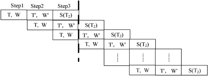
The pipeline process of three-step TW-MSD adder.
Assume that the reconstruction time of the TOP is T0, the number of processor bits is G, the number of operation (clock) cycles is Ty. So the amount of resource of processing the instance is G*Ty + T0. The TOP’s reconstruction time is 1 clock cycle, an addition operation needs 3 clock cycles. Suppose that an operation cycle is a clock cycle. For the instance, the computational efficiency of traditional model and dual-center model can be compared in consumed time and resource utilization, as shown in Table 2. It is shown that the clock cycle on dual-center model is only 0.2608% of on a traditional computer, and the computing resource spent on dual-center model is 25.04% of that on a traditional computer.
Through the experiments, it is known that each step of the experimental design is completed correctly, which indicates that the dual-center model is correct. In the model, the resource control software related to the TOP runs on electronic computer, so the science and technologies of electronic computer can be fully utilized, the utilization of the TOP is also improved. And when the TOP calculates the data in the ZHSL.SZG file, user’s electronic computer can handle other tasks. It achieves cooperative work for the same task between the TOC and electronic computer and keeps programmer’s programming habits.
The SZG file method is also its limitations. If the TOP cannot calculate 1000 times after one reconstruction, the two-center model is inferior to traditional computer. For large applications, if the intermediate calculation result data requires multiple iterations, the two-center model is also more troublesome than traditional computer, because the intermediate SZG files need to generate multiple times. The two-center model is best suitable for repeated calculation with massive data, without intermediate outcome data for multiple calculations. In the future, the two-center model needs to be improved, and the most likely method is to add a large memory to the TOP in the server, the large memory temporarily holds the intermediate result data for the next calculation, saving the time for the generation and parsing of SZG files.
link


